Technical Review of ADR
Over the last 20 years the increase in popularity of off-road driving has resulted in drivers, who are more skilled and better trained in the use of recovery equipment.
But are we aware of the damage recovering a modern coil sprung Land Rovers using the old techniques?
The typical off-road driver today is familiar with a wide range of techniques to enable the recovery of his or her vehicle from every possible situation, but not everyone understands just how the very high forces involved in recovery, act on the vehicle to create stress and strain on chassis and other components.
To understand how these forces act on the chassis and the suspension components we should take a minute to look at the development of the Land Rover.
The suspension systems of off-road vehicles have changed a lot in the last fifty years.
After the last world war the Jeep and then the Land Rover utilised leaf springs and these had both advantages and disadvantages:
The two advantages of the leaf spring are:-
Firstly, the individual leaves of the spring twist against each other as the vehicle rolls on a corner and this gives the suspension inherent roll resistance.
The second advantage of the leaf spring is forgotten by most of us. The top leaf of the front spring transmits all the recovery forces from winch or cable directly from the front of the chassis down to the axle and wheel. Thus saving the chassis and other suspension components from stress.
The disadvantages of leaf spring suspension are:-
The leaf spring does not offer as good axle articulation as coil springs and subsequently the Wheels’ of the vehicle may leave the ground and loose traction. Off road vehicles tend to be heavy and thus their leaf springs are thicker. This can give a harsh ride in some models.
Leaf springs are very exposed to dirt and water and therefore tend to rust, leading to severe
frictional damping. After some years the ride can become intolerable.
When a vehicle is recovered from mud or other condition the recovery rope is applied at the front of the chassis. (See Fig 1.)
The load on the recovery rope is resisted by the force offered by the ground against the wheels.
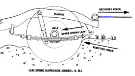
FIG 1.
The force is directed from the front of the chassis directly through the front spring hanger and along the top leaf of the spring to the axle. Thus the forces of recovery are resolved with little loading on the chassis.
With the advent of the Range Rover, coil springs were used to replace the leaf spring and this gave much increased axle articulation and a more comfortable ride. Because coils offer little roll resistance the manufacturers were forced to fit anti-roll bars front and back to provide roll
resistance.
Chassis Stresses during Recovery.
Any experienced off-road driver will tell you that the circumstances of ground condition and
inclination are too numerous to mention.
Recovery itself is achieved by winch, rope pull from another vehicle, kinetic pull from another vehicle and a good dose of skill with a sprinkling of luck.
In most circumstances the vehicle to be recovered is held fast in ground by its wheels, which have lost traction or cannot overcome the force resisting the wheels.
Analysis of the forces acting on the chassis and suspension components during recovery does allow us to understand exactly how severe these forces can be.
Land Rover, Range Rover and Discovery all have coil springs and their live front axle is located against forces in line with the chassis by radius arms which are mounted on the chassis beneath the A pillar of the vehicle. At the rear further radius arms and an A frame provide location. To locate the front axle square to the chassis and to locate it against side forces, a Panhard Rod is mounted from the chassis on one side to the axle on the other.
If the wheels of a coil-sprung Land Rover are deeply embedded in soft mud, when recovery occurs the greatest force resisting the movement of the vehicle is applied against the front wheels.
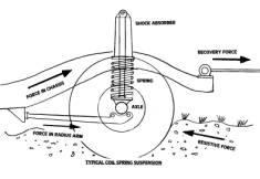
FIG 2
If we use the winch to recover the vehicle the recovery force acts through the winch mountings, back through the chassis to the radius arm mountings under the drivers door and then forward to the axle. Because the force of resistance against the wheel and the line of force of recovery are displaced from each other by up to 400mm there is a resultant vertical force created. If there is any angle in the line of cable the effect of this force is seen to open up the suspension and this can continue until prevented by the stops in the shock-absorbers or by limit straps if fitted.
If all the force available from a 9000lbf winch were used to pull a vehicle the shock-absorber stops could suffer a 2500lbf load each. A further problem can occur when we recover mired vehicles and attach the cable to the front of the chassis. Good practice dictates the use of a sliding bridle between the attachment points on each of the rails of the chassis. This allows the recovery cable to take up a natural position between the two chassis rails and thus the force of recovery is better distributed between the two. Although this expedient does prevent all the recovery force from being concentrated on one chassis rail it still does not load them equally.
In severe or kinetic recovery, forces are generated that lead to twisting of the chassis and the only way we realise that there is damage is when we notice uneven tyre wear.
When the stuck vehicle is recovered using a winch on another vehicle, a tow from another vehicle or a kinetic tow then the forces are transmitted through chassis and suspension components in the same way each time. Kinetic recovery utilises a rope that can stretch and store energy. This allows the vehicle pulling the rope to accelerate at some speed against the rope and thus the kinetic energy created by the momentum of the vehicle magnifies the force available to pull the mired vehicle out.
Kinetic recovery creates the greatest forces on vehicle chassis and suspension and is often to blame for damage to these essential components of Land Rovers.
The suspension components and chassis of all vehicles are designed to accept forces from the weight of the car, cornering, acceleration and braking. The suspension and chassis of the Land Rover can probably accept ten times the forces experienced by an on road saloon car and thus is able to meet most of the impacts and severe stress from off-road use. Extreme recovery forces are translated as stress in chain of components; the chassis is pulled into tension but because there are curves over the axle these forces can produce bending. The bracket under the driver’s door is loaded in shear and suffers bending moments as the recovery force is transferred forward along the radius arm as a compressive stress. Because the radius arm is relatively narrow it is described as a strut and is thus susceptible to bending.
Over the last 20 years there has been much development of the equipment we use for recovery. The duty cycle of electric winches has been greatly extended, we now have hydraulic winches with an acceptable speed of operation, but there has been no real change in techniques to take account of coil spring suspension.
We are still pulling our Land Rovers out of the muck as if they had leaf springs even though the coil spring has seriously changed the game-plan.
So perhaps it is time we applied some lateral thinking to the recovery of coil sprung
Land Rovers.
Have you ever looked at your Land Rover, Range Rover, Freelander or Disco stuck in the soft brown stuff up to the bumper and thought “If only I could reach down through the mud and hook my recovery cable onto the axle, where the pull of the cable would assist recovery by pulling the wheel up and out!”
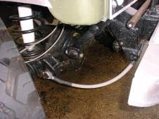
The answer to all of this is a new patented invention called ADR (Axle Direct Recovery). Nine millimetre galvanised steel cable is formed into a fixed bridle with an eyelet in the middle and one at each end. Each eyelet at the end is attached to a longer 16mm bolt passing through the front attachment bush of the radius arm, where it is fitted to the axle. The middle eyelet is brought up to a convenient place in the middle of the bumper where it accessible above bumper level.
The first 400 mm of cable up from the radius arm bolt on either side is sheathed in polyethylene tube to give it day to day protection from salt and road dirt and to impart a curvature. The cables are attached to any convenient holes in the chassis and the curve lent by the plastic pipe ensures that in all circumstances the cables are well clear of panhard rod and steering linkages.
It is the sacrificial attachment of the cables to the chassis that brings the spark of innovation to this invention. The cable sits there attached to your axle until you need it. When you attach your recovery cable to the middle eyelet of the ADR and then apply a pull, the sacrificial ties each side break and you are then pulling the front axle upwards and out. (See fig 3.)
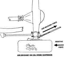
FIG 3.
All the recovery pull is now concentrated just inboard of the wheel at a place which can
accept forces and bending moments much, much higher than the chassis without risk of
damage.
Apart from attaching a cable to the wheel itself we could not get the recovery force nearer the resistive force! The chassis and suspension are now left to do the job they were designed for ...carrying the weight of the vehicle!
As soon as recovery is complete it only takes a minute to re-attach the sacrificial ties each side.
When we pulled the vehicle from each chassis rails we had to use a sliding bridle to even up the forces but this can lead to side slippage as the cable moves one way and Land Rover goes the other. This is not always a problem but can be when you are on a compound slope near trees or walls.
Because the mounting of ADR at each end of the axle can accept much higher loads than the chassis mountings we can fix the middle eyelet in the centre of the ADR bridle and no longer worry about the distribution of load. This doesn’t completely stop the vehicle slipping sideways, but it does give a much better standard of control on the recovery cable.
Once out of the muck it only takes a minute to re-attach the sacrificial mountings at each side and hook the middle eyelet up and out of the way and we are then ready to go and get stuck again.
The mounting of ADR is the same on the front of all coil sprung Land Rovers
although the choice of location for the sacrificial ties requires a little thought, bearing in mind that the ADR cable must flex with the movement of the axle and extend to articulation limits.
ADR can also be mounted at the rear of most Land Rovers where it can be just as effective.
Because of the high forces involved, off road training programmes place great emphasis on safety in all aspects of recovery. There are far too many unsuitable attachment points on modern vehicles such as lashing rings and bumper brackets that can lead to accidents. ADR provides a safe and tested attachment point to reduce the risk for the off-road enthusiast and the professional.
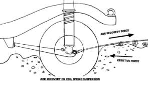
FIG 4.
ADR is subject to a World Wide Patent Application
We are very grateful to the team at Protrax for their testing of ADR and especially to Vince Cobley for his encouragement
ADR has been developed by Airmuscle Limited, who are well known for the wide variety of technology they have developed over the last 20 years, including the Tactile Gloves used by NASA for remote sensing in outer space, Motion Simulators for theatres in Hong Kong, Virtual-RealityVehicles for pilot evaluation by the US Navy, and the Actuator and Computers that animated the famous Spitting Image Puppets in exhibitions. Airmuscle have a Discovery and a Land Rover hybrid and the Managing Director bought his first Series 1 in 1960 and is now on his third!
ADR is available from YiCaN Pty Ltd, Frankston, VIC, Australia.
It takes about 30 minutes to fit to a Land Rover (depending on the condition of your radius arm bolts!)
It comes with all bolts, parts, complete instructions and a one year guarantee.
ADR will be available at stockists so please check with your local Off-Road specialist.
Australia Fax: 61-3-9787 9228 Tel: 61-3-9775 2279 Web: yican.com.au Inquiry: adr@yican.com.au |